

Under BS 7671, RCD verification means an alternating current test at the device’s rated residual operating current (IΔn): general (non-delay) types must disconnect within the regulatory maximum disconnection time, while Type S devices must operate within the required operating time band specified for Type S devices. That single test, defined against BS 7671, BS EN 61008/61009 and BS EN 61557-6, sits at the centre of every compliant testing programme, with the IET providing the working guidance most engineers follow. Frequency itself isn’t fixed; it’s risk-assessed and recorded through EICR and PPM cycles.
TL;DR:
- RCD verification under BS 7671 requires just one alternating current test at the device’s rated residual current, confirming it trips within the specified disconnection time.
- The testing focus is on ensuring the device functions as installed, not on manufacturer type testing or multiple diagnostic tests, which are no longer required by regulations.
- Connection accuracy, proper phase angle testing, and compliance with standard BS EN 61557-6 are crucial for valid test results, with specific attention needed for modern circuits like EV chargers and embedded generation.
- Testing intervals should be risk-assessed and documented, typically annually for high-risk environments and every five years for low-risk sites, with detailed records to support compliance.
- Passing a simple AC trip test does not guarantee suitability for circuits with bidirectional current or additional complex configurations, which require proper judgment and potentially specialized testing.
What BS 7671 (A4:2026) actually requires for RCD verification
Regulation 643.7 and 643.8 set out the verification duty for residual current devices, and the requirement is narrower than many facilities teams assume. It calls for one AC test at IΔn, timed against the disconnection limits stated above. There’s no requirement in BS 7671 itself to run every diagnostic multiple a tester offers, only to confirm the device trips within its rated time when subjected to its rated residual current.
This matters because earlier editions of the regulations, via the now-removed Appendix 3 Table 3A, gave inspectors a wider table of test currents and expected times that blurred the line between verification and manufacturer type testing. That table is gone. What remains is a cleaner distinction: BS 7671 verification confirms the device works as installed, while manufacturer type testing, governed by BS EN 61008 for RCCBs and BS EN 61009 for RCBOs, confirms the device meets its design specification before it ever reaches site. An inspector’s job is the former, not the latter.
Amendment 4:2026 reinforces this by pushing inspectors to think harder about what sits on either side of the device being tested, particularly where solar PV, battery storage or EV charging introduce current flowing in directions the original design never anticipated. The verification test itself hasn’t changed. What’s changed is the judgement required around it: an RCD that passes a straightforward AC test at IΔn may still be unsuitable for a circuit carrying bidirectional current, and BSI’s guidance makes clear that inspectors need to flag that mismatch rather than treat a pass as the end of the story.
For facilities managers, the practical takeaway is simple: know which regulation your test evidences (643.7/643.8), and don’t confuse a passed verification with a statement that the device is the right type for the circuit it protects.
Standard RCD test sequence and pass/fail criteria used in practice
Before any instrument touches a circuit, the integral test button gets pressed. It’s a mechanical check, confirming the device can physically trip, not a timing measurement, and it tells you nothing about disconnection speed. The real verification starts once a proven multifunction tester (proved on a known source before and, ideally, after the test) is connected correctly.
The sequence most engineers follow on site runs like this:
- half the rated residual current diagnostic test — the device should not trip; if it does, that points to a fault, nuisance tripping risk, or leakage current already close to the threshold.
- timed test at rated residual current at 0 degree phase angle — the pass/fail measurement against the regulatory limit (within the regulatory maximum disconnection time general type; timing band required for Type S time-delayed devices).
- timed test at rated residual current at 180 degree phase angle — repeated on the opposite phase angle, since electromechanical RCDs can behave asymmetrically depending on the half-cycle the fault current starts on.
- higher-multiple fault current and ramp tests commonly used for diagnostics but not required by BS 7671 — not a BS 7671 requirement, but widely used because it stress-tests the device beyond its rated point.
Statistic to flag: the commonly quoted a characteristic disconnection time drawn from product standards at five times rated residual current doesn’t come from BS 7671 at all. It’s a characteristic drawn from the product standards, BS EN 61008 and BS EN 61009, and engineers use it as a useful diagnostic ceiling rather than a statutory pass mark.
Record the longer of the 0° and 180° readings as the result that goes on the certificate, since that’s the worse-case figure a real fault would encounter. A result sitting close to the regulatory maximum disconnection time ceiling, say 280 to 295 ms, isn’t an automatic fail, but it’s worth flagging as an observation and revisiting at the next inspection, particularly on an ageing device.
How often should RCDs be tested?
There’s no single statutory interval for instrument-based RCD testing written into BS 7671. That surprises a lot of newly appointed compliance managers, who expect a neat annual figure. Instead, the regulations expect frequency to come from a documented risk assessment, tied into the periodic inspection cycle and whatever PPM regime already covers the site.
Two testing types run in parallel, and it’s worth keeping them separate:
- Occupant push-button checks, required regularly as required by BS 7671 Regulation 514.12.2, are a functional check anyone on site can perform.
- Instrument-based verification, carried out by a competent person with proven test equipment, follows the risk-assessed schedule set for the building.
Typical bands seen across commercial estates: annual testing for higher-risk environments (healthcare, industrial plant, sites with embedded generation), and testing aligned to a five-yearly EICR cycle for lower-risk offices and retail units, often with interim checks built into a PPM contract.
Pro Tip: Write the rationale for your chosen interval directly onto the PPM schedule, not just the test result. An inspector five years from now needs to see why annual testing was chosen for that specific site, not just that it happened.
Test instruments, connection method and practical test setup
BS EN 61557-6 sets the standard for the instruments themselves, and it’s not optional reading. A tester that doesn’t meet this standard shouldn’t be used for statutory verification, whatever its display claims to show.
Before any test result counts, prove the instrument on a known source, both before and after the session, to confirm it’s still reading accurately. Skipping this step is one of the most common reasons a result gets challenged later.
Connection matters as much as the instrument:
- Connect between the line terminal downstream of the RCD and the main earth, never the neutral, since an incorrect connection can produce a plausible-looking but invalid result.
- Where practicable, disconnect outgoing wiring before testing to stop connected loads or leakage from skewing the reading, a point the IET’s guidance on minimising unnecessary live testing sets out clearly.
- Test at both 0° and 180° phase angles, since the two readings can differ, and take the longer as the result of record.
Pro Tip: Check lead condition and instrument calibration certificates before every session. A cracked lead or an out-of-date calibration invalidates the entire test, no matter how carefully the connection was made.
Live working around consumer units and distribution boards carries its own risk assessment obligations; isolate where possible, and treat any test on a live board as a task requiring appropriate PPE and a second competent person where site rules demand it.
Special cases: type S, integral devices, EV chargers and embedded generation
Modern installations complicate what used to be a fairly uniform test. A few categories now need specific attention:
- Type S devices require both ends of the timing band respected, 130 to 500 ms. Tripping faster than 130 ms isn’t a pass; it means the device has lost its time-delay discrimination function against downstream RCDs, defeating the point of fitting it.
- RDC-DD and RDC-PD devices, integral to equipment such as EV chargers rather than separate consumer unit modules, follow test intervals set by the manufacturer, and BS 7671 expects those manufacturer instructions to be followed and documented, not substituted with a generic schedule.
- EV chargers and embedded generation introduce bidirectional current paths that a simple pass/fail AC test may not fully characterise; A4:2026 guidance expects inspectors to note where a protective device’s type may not suit the actual current flow. On charger circuits specifically, installer guidance on Type B and RDC-DD selection is a useful reference when deciding whether the fitted device is even the right category to begin with.
- Cascaded RCDs need testing in a sequence that avoids one device’s trip masking another’s fault; test the downstream device first, isolate as needed, and don’t assume an upstream trip during a downstream test is a false fail without checking discrimination timing first.
Recording results and reporting on the EICR
Every test needs enough detail on record that a different engineer, years later, can understand exactly what was checked and why. That means noting the device’s location and identification, its type (general, Type S, RDC-DD), its rated IΔn, and the worst-case trip time recorded at 0° or 180°.
Where a device fails or performs marginally, EICR observation codes carry the weight:
- C1 — danger present, immediate action required.
- C2 — potentially dangerous, requiring urgent remedial attention; most RCD trip-time failures land here.
- C3 — improvement recommended, not a compliance failure in itself.
Retain evidence, including proving records and instrument calibration certificates, for the client’s compliance file, and confirm the six-monthly push-button instruction has been handed to the responsible person on site, not just performed once by the engineer.
Common testing pitfalls and when to replace an RCD
- Connected loads skewing readings — isolate outgoing circuits before testing where practicable; a “failed” result is often just leakage current from equipment still connected.
- Incorrect connection — a line-to-neutral connection instead of line-to-earth produces meaningless numbers; recheck the setup before condemning the device.
- Instrument limitations — not every multifunction tester handles DC component testing correctly; check manufacturer data before assuming the device itself is faulty.
- Genuine borderline or failed trip times — if isolation and a retest confirm the fault, log it as a C2 and schedule remedial replacement rather than retesting repeatedly hoping for a different result.
How Delta First builds RCD verification into planned maintenance
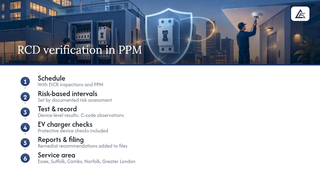
Delta First schedules RCD verification alongside EICR inspections and PPM contracts, so testing intervals reflect a documented risk assessment rather than guesswork. Reports include device-level results, C-code observations and remedial recommendations, feeding directly into client compliance files. Our engineers also cover EV charger protective device checks as part of wider electrical maintenance across Essex, Suffolk, Norfolk and Greater London.
Author’s perspective: practical priorities for compliance managers
Most testing gaps I see aren’t about ignorance of the regulation, they’re about resource allocation. Prioritise life-safety circuits and any embedded generation first; align RCD verification timing with your EICR recommendations rather than running them as separate exercises. Beyond that, invest in properly proven instruments and genuinely competent engineers. When a device’s behaviour looks ambiguous, check manufacturer data before assuming the regulation has an answer it doesn’t.
— Ashley
Request an RCD testing and compliance survey from Delta First
Delta First is the practical route to meeting RCD testing requirements without building an in-house compliance team from scratch. We deliver EICR inspections, scheduled RCD verification within PPM contracts, and remedial replacement work, all backed by bespoke reporting your compliance file can rely on.

Whether you’re managing a single site or a portfolio across Essex, Suffolk, Norfolk or Greater London, getting a risk-assessed testing schedule in place now avoids the scramble of a failed inspection later. If you’re also reviewing wider electrical works, our commercial electrical contractors team can scope that alongside your compliance survey. Request a quotation or arrange a planned maintenance survey with Delta First, and get your RCD verification schedule properly documented before your next EICR is due.
Need help with your electrical installation or compliance? Delta First’s directly employed electricians provide testing, maintenance, installations and upgrades for commercial and residential properties across Essex, Suffolk and London, with 24/7 emergency cover. Call 01206 237422 or request a quote.
Sources
Recommended
- Fixed wire testing: your commercial compliance duties
- Commercial EICR Essex | Electrical Testing
- 7 key checks: CDM 2015 client duties for UK facilities managers
- Act now: written scheme of examination for UK facilities managers
Talk to Delta First
Delta First Building Services is a Colchester-based M&E contractor working across Essex, Suffolk and London, with commercial work in Norfolk. Our directly employed electrical team is supported by vetted specialist subcontractors where extra certification is needed, and we offer genuine 24/7 emergency cover. Get in touch to arrange a survey or quote.