

Power factor correction reduces reactive power drawn from the grid, cuts supplier charges, and frees usable transformer capacity for the same site load. Most commercial and industrial sites should target a power factor between 0.95 and 0.98. If your last bill shows a reactive power or “kVArh” charge, or you haven’t checked your half-hourly metering data in the last year, that’s the immediate next step before ordering any equipment.
TL;DR:
- Correctly sizing power factor correction equipment requires a harmonic assessment, especially if non-linear loads exceed 15% of transformer kVA.
- Improving power factor from 0.7 to 0.95 can increase available transformer capacity by approximately 36%, potentially avoiding upgrade costs.
- Installing proper correction equipment reduces thermal stress on assets, extends their lifespan, and improves system efficiency beyond billing savings.
- A comprehensive site survey, including half-hourly metering and harmonic analysis, is essential for choosing the right correction method.
- Power factor correction should be viewed as a maintenance measure that protects assets and optimizes capacity, not just a quick fix for reactive power charges.
Table of Contents
- What is power factor correction and how does it work?
- Why correction matters for billing, capacity and asset health
- Types of power factor correction and where each one fits
- How to calculate the power factor correction you need
- Harmonics, modern loads and where correction can go wrong
- Specifying and accepting a PFC installation: what to check
- Delta First’s approach to power factor correction
- An editorial view on treating power factor as maintenance, not just cost
- Request a power factor site survey from Deltafirst
- Sources
What is power factor correction and how does it work?
Power factor measures how efficiently electrical current is converted into useful work. It’s the ratio of real power (kW), which drives motors and lights, to apparent power (kVA), which is what your supply actually has to deliver. The gap between the two is reactive power (kVAr), created by the magnetic fields in motors, transformers, and fluorescent ballasts.
Correction works by installing capacitors that generate leading kVAr to cancel out the lagging reactive current drawn by inductive equipment. The site then draws less total current for the same useful output.
Uncorrected power factor varies significantly by equipment type:
- Resistive loads (heating, incandescent lighting): close to 1.0, needing little or no correction
- Fluorescent and discharge lighting: typically 0.5 to 0.6 uncorrected
- Induction motors, especially lightly loaded ones: often 0.6 to 0.8
- Welding and arc equipment: can drop as low as 0.5
Why correction matters for billing, capacity and asset health
Most UK distribution network operators apply reactive power charges once average power factor falls below a commonly targeted threshold near 0.95, a threshold reflected in wider government energy efficiency guidance. That charge appears on your DUoS billing line, often overlooked because it’s buried beneath standing charges and unit rates rather than flagged as a separate cost centre.
The capacity gain is the part most facilities teams underestimate. Improving power factor from 0.7 to 0.95 can increase the usable kW you can draw from the same transformer by roughly 36%. That’s often enough to defer a transformer upgrade entirely when a site is expanding.
There’s a knock-on asset-health benefit too:
- Lower current draw means less heat in cables, busbars, and switchgear
- Reduced thermal stress cuts nuisance tripping on protective devices
- Equipment operating closer to its rated current tends to last longer before failure
- Correcting power factor can also lower copper losses and carbon emissions, a point recognised in some building regulations energy performance calculations
Types of power factor correction and where each one fits
Choosing the right correction method depends on load type, load variability, and how much non-linear (harmonic-generating) equipment sits on your system.
- Fixed capacitors suit constant loads, such as a single large motor, where reactive demand doesn’t fluctuate through the day.
- Automatic power factor correction (APFC) panels switch capacitor banks in and out to track a varying load, making them the standard choice for most commercial and mixed-use buildings.
- Detuned banks, which add a reactor in series with the capacitor, shift the resonant frequency away from common harmonics and suit sites with a meaningful share of variable-speed drives, LED drivers, or UPS systems.
- Static VAR compensators (SVCs) and active filters respond dynamically and handle sites with heavy, fast-changing non-linear loads that detuned banks can’t fully manage.
Central correction at the main incomer suits sites with genuinely varying loads across departments. Local correction fitted at individual motor terminals reduces copper losses on the cable run to that motor but won’t necessarily bring the whole site up to target power factor on its own.
Pro Tip: Before specifying anything, ask for a breakdown of non-linear load as a percentage of transformer kVA. That single figure decides whether you need standard APFC, a detuned bank, or active filtering.
How to calculate the power factor correction you need
The core formulae are straightforward, and worth keeping on file even if an engineer does the final sizing:
- Power factor: PF = kW ÷ kVA
- Reactive power: kVAr = √(kVA² − kW²)
- Required capacitor size: capacitor kVAr = kW × (tan θ1 − tan θ2), where θ1 and θ2 correspond to your current and target power factor angles
A worked example makes this concrete. A site drawing 100 kW at a power factor of 0.75, wanting to reach 0.95, needs roughly 55 kVAr of correction. That’s the gap between the reactive power your load currently demands and the reactive power it needs once corrected.
The inputs matter as much as the formula. Half-hourly meter data spanning a full billing cycle gives a far more reliable picture than a single spot reading, particularly on sites where load shifts across shifts or seasons. A spot reading taken on a quiet Tuesday afternoon can flatter your actual position considerably.
Harmonics, modern loads and where correction can go wrong
Standard power factor correction measures displacement power factor, the phase shift between voltage and current. On sites with distorted waveforms, that number can look fine while the true RMS power factor tells a different story entirely. Harmonics from variable-speed drives, LED lighting, and switched-mode power supplies distort the current waveform in ways a simple displacement reading won’t catch.
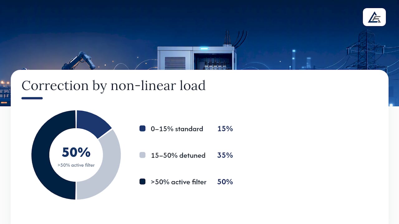
As a rule of thumb, standard capacitor banks are fine below around 15% non-linear load relative to transformer kVA. Between roughly 15% and 50%, detuned banks are recommended. Above that, active filtering becomes the safer route.
The risks of getting this wrong are specific, not theoretical:
- Resonance between capacitors and system inductance can amplify harmonic voltages rather than absorb them
- Capacitors sized without accounting for harmonics can overheat and fail prematurely
- Sites running standby generators can see instability if corrected power factor swings leading during light-load periods
- PV generation can cause capacitor banks to cycle excessively as site demand fluctuates through the day
Specifying and accepting a PFC installation: what to check
A well-written specification avoids most of the problems that surface after commissioning. Before signing off any bid, confirm the following is included:
- A harmonic assessment identifying non-linear load as a percentage of site kVA
- A clear statement on whether standard, detuned, or active correction is required, and why
- Capacitor-duty rated contactors, not standard motor contactors, which aren’t built for the switching duty capacitors demand
- Pre-charge resistors to limit inrush current on switching
- An APFC staging strategy that matches step sizes to your actual load variation, not a generic default
Installation location matters too: central correction at the main incomer versus local correction at specific motors each carries different maintenance access implications, and your specification should state which applies where.
Pro Tip: Treat a missing harmonic study, undersized contactors, or the absence of any stated maintenance plan as red flags in a bid, not minor omissions to query later.
Delta First’s approach to power factor correction
Power factor correction can be treated as an asset-health measure, not just a one-off billing fix. Reduced current draw means less thermal stress on cables, switchgear, and transformers, which is exactly the kind of intervention that belongs inside a planned preventative maintenance programme rather than bolted on as an afterthought.
Qualified engineers can assess site load profiles, specify correction equipment suited to your harmonic profile, and build ongoing checks into an existing planned preventative maintenance (PPM) contract. If your site hasn’t had a power quality review recently, that’s the sensible starting point.
An editorial view on treating power factor as maintenance, not just cost
Most guidance on this subject still frames power factor correction purely as a billing exercise: find the reactive charge, install capacitors, save money. That framing isn’t wrong, but it’s incomplete, and it leads plenty of estates teams to under-specify equipment because they’re optimising for the invoice rather than the asset.
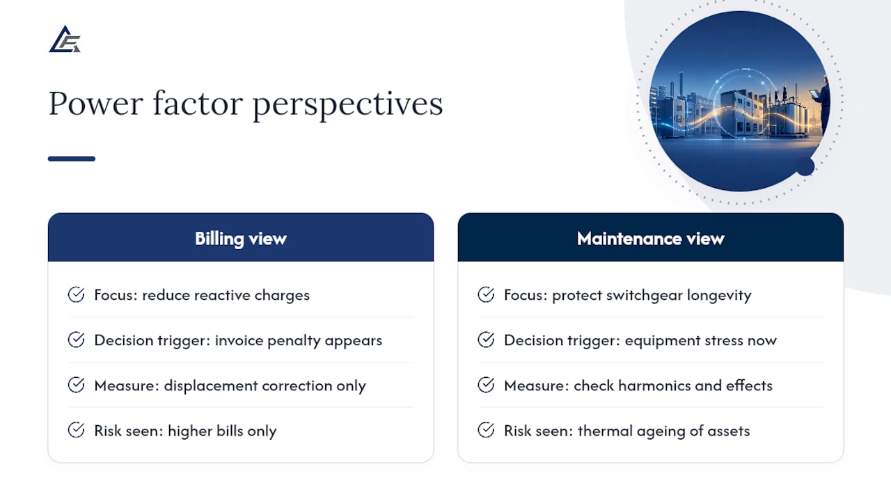
The better question isn’t “what’s my payback period?” It’s “what is uncorrected power factor doing to my switchgear right now?” Elevated current draw shortens the working life of contactors, busbars, and cable insulation quietly, long before anyone notices a fault. Facilities teams who wait for a reactive charge to appear on a bill before acting have usually already absorbed years of avoidable thermal stress.
The other gap in conventional advice is harmonics. A lot of installed capacitor banks were specified before variable-speed drives, LED lighting, and on-site PV became standard, and nobody has revisited whether displacement-only correction still fits the load. If your site has added any of that equipment in the last five years, get the harmonic content checked before you assume last decade’s capacitor bank is still doing its job properly.
— Ashley
Request a power factor site survey from Deltafirst
Deltafirst is the practical route to power factor correction that doesn’t leave you guessing whether the equipment fits your actual load. As a commercial building services contractor, we assess your site’s reactive power profile, specify correction equipment matched to your harmonic content, and can fold ongoing checks into a planned maintenance contract rather than treating it as a one-off job.

A site survey covers half-hourly metering review, a harmonic assessment where non-linear loads warrant it, and a sizing recommendation you can act on immediately or hand to your own procurement process. From there, installation can run as a standalone project or sit inside an existing PPM agreement covering your wider electrical estate.
If you manage a commercial site across Essex, Suffolk, Cambridgeshire, Norfolk, or Greater London and want a clearer picture of what correction could save on capacity and maintenance costs, get in touch to arrange a survey through our commercial electrical services team or request a quotation for your site.
Sources
- Gov
- Power Factor Calculator — Correction & Capacitor Sizing | TradeCalculator
- Power Factor Correction & Harmonics: A Technical Guide for UK Electricians – Voltimum UK
- Power Factor Correction – Capacitor Sizing Guide | E‑Das Company